General Principles
- The wall thickness of the substrate and overmold should be as uniform as possible to obtain the best cycle time. Transitions between wall thickness should be gradual to reduce flow problems such as back fills and gas traps.
- Wall thickness in the range from 0.060" to 0.120" will ensure good bonding in most overmolding applications.
- If the part requires the use of thick sections, they should be cored out to minimize shrinkage problems and to reduce the part weight.
- The use of radii (0.020" minimum) in sharp corners helps reduce localized stress. Deep unventable blind pockets or ribs should be avoided.
- Long draws should have a 3° - 5° draft to help ejection.
- Properly designed deep undercuts are possible with GLS overmold TPEs. Care should be taken to minimize sharp corners. An advancing core should be used when the mold opens and the elastomer should be allowed to deflect as it is ejected.
Flow Length and Wall Thickness
Spiral flow testing results for GLS products are presented below using injection speeds of 3 in/sec and 5 in/sec. Special TPEs can achieve up to 40 inches at an injection speed of 5 in/sec.
|
Series
|
Flow Length at 3 in/s
|
Flow Length at 5 in/s
|
|
Dynaflex D
|
13-15
|
18-20
|
|
Dynaflex G
|
12-22
|
18-30
|
|
Versaflex
|
9-16
|
13-26
|
|
Versalloy
|
18-20
|
30-32
|
|
Versollan
|
9-16
|
13-26
|
|
Spiral flow test performed using 0.0625" x 0.375" channel at 400°F
|
Shrinkage and Warpage
Most GLS styrenic TPEs (Dynaflex and some Versaflex) have fairly high mold shrinkage and cause the overmolding TPE to contract more than the substrate, which can result in warpage or cupping of the substrate part. This is especially true for long, thin parts or parts where the substrate is thinner than the overmold or if a low modulus substrate material is used.
This can be managed in several ways:
- Use a higher modulus substrate material
- Add stiffening ribs to the substrate part
- Minimize the thickness of the soft TPE
- Use a lower hardness for the TPE
- Relocate the gate to minimize the flow length to thickness ratio
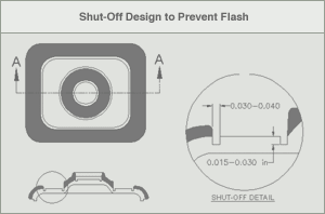
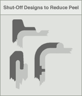
Shut-Off Design
Shut-offs should be designed to:
- Reduce the potential of peeling and provide a sharp transition between the TPE and the substrate.
- Provide a distinct cavity for the TPE that is capable of being vented.
- Prevent the TPE from flashing over areas on the substrate.
- Provide a 0.003" to 0.005" (0.076 mm to 0.127 mm) interference when using plastic inserts or substrates, to take into account shrinkage, sinks and tolerances.
- Provide a spring-loaded area if the inserted substrate is a metal or other non-compressible material.
An accent groove of 0.015" to 0.030" (0.381 mm to 0.762 mm) depth and 0.030" to 0.040" (0.762 mm to 1.02 mm) width helps to develop a good shut-off.
Due to the tolerance on metal and other non-compressible inserts, it is necessary to include Belleville disc springs (or high tension springs) in the design to prevent flashing of minimal thickness inserts or crushing of oversized inserts.
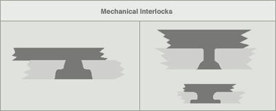
Mechanical Interlock Designs
Mechanical interlocks are used in overmolding to improve attachment to the substrate in areas subject to high stress or abrasion. A few examples of mechanical interlock designs are shown below: